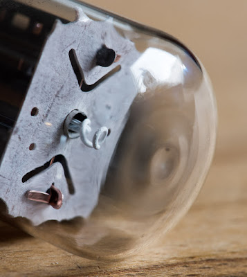
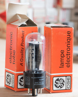
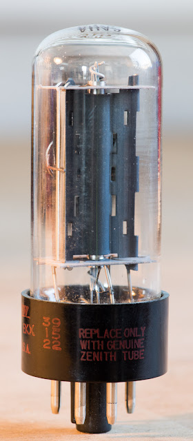
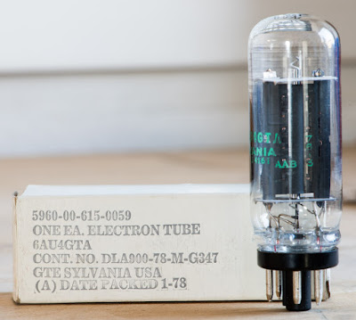
After the presentation of the very early rectifier tube in last months ToM post, let's continue the rectifier theme. This months tube is a TV damper, the 6AU4.
I covered many TV dampers already, the 6BY5, 6BE3, 6CG3, 6CJ3, 6DQ4 and my favourite one, the 6AX4 and a 25 heater variant of it, the 25AX4.
 I like to use the 6AX4 due to it's lower heater power. It's current handling capability is sufficient for most audio applications. If very high B+ current is needed, 6CG3 or 6CJ3 are well suited candidates. But they have different sockets. If an octal socket is preferred but more current is needed than the 6AX4 can handle, the 6AU4 might fit the bill. It shares the same pinout with other octal TV dampers. The increased current capability comes at a price, it also needs more heater current. 1.8A versus the moderate 1.2A of the 6AX4. Like the other TV dampers it contains only one diode. The only exception is the 6BY5 which has two diodes in a single bottle. This means two 6AU4 are needed for a full wave rectifier, which requires 3.6A heater current. Or 4 of them in an all tube bridge rectifier which would need a whopping 7.2A of heater current. Like the other TV dampers it has very high voltage capabilities and can also handle large voltage differences between heater and cathode.
 This is limited to the heater negative to the cathode however which is allowed to go up to 900V DC. In the other case with the heater positive to the cathode themaiimum allowed is 300V DC. In actual implementations it is advisable to stay well clear of those limits. I typically use such tubes with the heater voltage referenced to ground and for DC output voltages up to 700V DC. Although the tube manufacturers never advised to use TV dampers for mains rectification purposes, they proved to be very well suited for such applications and have been working in the power supplies of my amps reliably for many years. I guess the tube manufacturers preferred to keep selling their more expensive rectifier tubes for power supplies. TV dampers were produced in the millions for TV sets and had to be cheap. Since they got produced in such large volumes they are still available in quantities at very low prices. The 6AU4 can be found as 6AU4GT and as 6AU4GTA. The GT simply stands for glass tube. The A was added after the tube was improved with slightly higher current handling capability.
Many of you are probably wondering where the name 'TV damper' comes from. So let's have a look at the actual application they were developed for. Before flat screens were introduced, TV sets had a cathode ray picture tube. These had an electron emitting cathode like other vacuum tubes. The cathode produced an electron beam which got modulated, accelerated and directed towards the front. In order to create a picture the beam had to move in a zig zag fashion from left to right and top to bottom. This was achieved by coil winnings arranged around the neck of the tube, which was called a yoke. Different yokes were used for the horizontal and vertical scanning. For this purpose the yolk had to be fed with a sawtooth current. This was generated by horizontal and vertical deflection circuits. Shown below is a very simplified drawing of the horizontal circuit. It typically used a beam power tetrode which was fed by a sawtooth voltage and coupled to the horizontal yoke through a transformer.
The problem with this is a parasitic oscillation set up in the transformer and yoke during flyback of the electron beam, caused by the sudden current cut off in the transformer at the end of each cycle when the magnetic fields collapse. This oscillation needed to be damped to avoid non linearities in the picture. This could be achieved with resistors or RC elements, but a more elegant way to do it is the use of a diode shunted across the secondary as shown in the next picture.
In later TV sets, the energy stored in the inductances of transformer and yoke was partially recovered. This was done by generating a boosted B+ voltage. Also the output transformer was usually replaced by an auto former.
The spikes generated by the collapse of the magnetic fields were used to charge a booster capacitor Cb and the voltage was added to the raw B+. Therefor TV dampers are also called booster diodes sometimes. The schematic above only shows the principle and is by no means accurate or complete. It is just meant to show the concept. In actual implementations this spike was also used to generate the very high ultor voltage of the picture tube through an additional winding which fed another very high voltage and very low current rectifier diode (not shown in the picture).
I hope this little excursion into TV sets enlightened the background of these tubes a little. For more detailed information you can refer to the website of the Early Television Museum. Now lets continue with some photos of various 6AU4 tubes, starting with Westinghouse of which I have various versions. One came in the beautiful boxes shown above and the other in rather bland packaging:
While the latter looks rather regular, the other with the getter applied in the top dome is quite different in construction.
A close up photo shows that it has a small glass piece at the top sitting above the mica disc:
I have never seen this in any other TV damper tube. Here a close up:
Probably done to get some extra strengthening. Here the same tube with power applied to the heater:
From another angle:
The top end of the other Westinghouse 6AU4 with more common construction style:
Another Westinghouse version came with the small 'coin base' as also seen on many other tubes. The coin base was introduced quite late and is a more modern construction style:
Here a comparison between coin base and regular style:
This one is in a Box marked Westinghouse Reliatron:
The plate has two extra wings for additional cooling
These are all the different Westinghouse 6AU4GT/A versions I have.
Up next let's have a look at Raytheon.
From this manufacturer I found 6AU4s in 3 different packagings and 6 different construction styles.
The first one looks quite ordinary like many other TV damper tubes. Clear glass top with the getter applied near the base, printing on the base.
The next one has a bit larger plate structure and looks more rugged.
This one is quite similar as the one before but different cutouts on the plate at the side and the glass is a bit taller:
Yet another minor difference in plate shape:
The next one has a very different plate structure with metal extending at 4 sides which should give better heat dissipation.
The getter applied at the top:
And lastly the one which appears to have the most rugged construction:
The top is also quite different with the spiral which isolates the heater from the cathode extending much further.
The spiral is also attached to a metal rod for some extra support.
Another view:
And lastly two tubes branded Lindal / LTT. Apparently a japanese company but the construction is identical to one of the versions above. So quite certainly made by Raytheon and rebranded.
This sums it up for Raytheon.
Moving on to General Electric.
Most GE 6AU4 I have, look very similar with only minor differences.
Sometimes only the color of printing or position of printing is changed.
These two differ in the plate material:
One has copper.
The other is made of a shiny silvery metal.
Both look remarkably similar to some GE 6AX4 I have, only the plates are slightly longer. So I had a closer look and was up for a surprise.
When I applied heater voltage to the copper version, it only drew less than 1.2A! That looks suspiciously like a 6AX4. Did they take some short cuts in production? The other one draws close to the nominal current:
For 6.3V heater tubes the nominal voltage should be close to spec but the current can vary, but this is some 30% below the datasheet value! This should be taken into account if designing for 6AU4. I doubt such a tube has the increased current capability over the 6AX4.
I also have some GE 6AU4 in military packaging. Unsurprisingly these draw the right current.
I am sure the military would not have accepted such a deviation from the data sheet value. But apparently they were a bit sloppy with the commercial tubes. I will examine this also for other brands.
Lastly 6AU4 by Canadian General Electric above, which concludes the GE section.
Next we have Tung-Sol.
This one looks quite regular.
A different version in another box style:
It is a bit longer than the other one.
Let's have a look at their heater current.
Both well in spec.
CBS:
An older version marked CBS Hytron
Later they dropped the Hytron name.
Both rather large bottles with long plates.
Quite different in construction.
Due to the large plates I expected the heater current to be in spec.
That's all I have from this manufacturer.
Up next DuMont which used to buy tubes from other manufacturers and sold them under their label.
The tubes were probably made by RCA.
Nice large construction and heater current in spec.
DuMont used very unique and beautiful gold coloured boxes.
4 different 6AU4 by Motorola:
They changed their company logo and tube packaging a lot.
Philco was another equipment manufacturer who sourced tubes from other companies and relabelled them.
Zenith also sourced their tubes from other manufacturers.
I have three versions of the Zenith brand:
Large base copper plate:
Large base regular plate:
And the same with coin base:
How do the heater currents compare?
The copper plate tube draws current more like a 6AX4:
The others are close to the nominal 1.8A:
That's all from Zenith.
I only have a few tubes from Amperex. Among them two different versions:
The one on the left looks suspiciously like a GE. It's heater current also measures low.
The other one has the famous bugle boy logo on the base.
And also has the larger construction with the proper heater current for a 6AU4.
Up next various brands of which I only have single tubes or very few. Most of these are house labels from store chains or otherwise rebranded tubes.
Lafayette:
Emerson:
Airline, unfortunately this tube is dead, as can be seen by the whitened getter:
United Electric:
BesTest:
'This one is completely unbranded:
Another 'no brand'. Boxes named Quality Brand and a very faint 'Delta' on the base:
Triad:
Rad-Tel:
IEC:
Truetone:
Selectron:
Magnavox:
Zalytron:
Since I have not enough of any of these to make a quartett, I did not bother measuring them. But they are nice additions to the tube box art collection.
Before we turn to the big boys in tube munaufaturing, let's have a look at the internal construction of a 6AU4 tube.
I picked one of the Westinghouse tubes with the unusual glass disc inside.
Removing the glass bottle gives a better view. There are 4 support rods molten into this glass disc.
Beneath the glass disc there is the usual mica which ensures the spacing between cathode and plate.
At the bottom there is another glass support disc.
Again with 4 rods molten into the glass.
Heater wire pulled out a bit:
The heater wire with the isolation spiral.
This spiral gives the very high voltage rating between heater and cathode.
The tip of the heater which consists of a folded wire:
Clipping the support rods which hold the plate and cathode partially pulled out:
The cathode still attached to the bottom mica:
The rim at the ends of the cathode clips into the mica discs:
The bottom glass disc. A piece broke off when I clipped the metal rods:
The pate:
Glass and mica disc from the top end:
The other side with the metal ring which held the getter during manufacturing:
The mica discs are held in place by small metal strips which are welded to the support rods:
Two of the large manufacturers remain to be covered. Here are the Sylvania 6AU4 tubes:
Let's start with the oldest versions a 6AU4GT (without 'A'):
A quick check of the current again showed 6AX4 type heater behaviour:
So this is clearly not a matter of vintage. At the end of the tube era it was common practice to use the same internals for different tube types which are close in spec, to save cost. But this tube is from the golden tube age.
Here we have another early 6AU4 which draws the right heater current:
And another one:
Next, two versions of 6AU4GTA. Both with the same internal construction but slightly different glass size:
And the same internal construction in a coin base bottle:
All three have heater currents in spec.
These tubes have the heater wires extending well outside the cathode and even the isolation spiral which makes the heater glow nicely visible:
And finally two Sylvania 6AU4GTA in military packaging.
A nice tube with green printing on the base.
As expected with heater current in spec.
A later version with coin base, made in the late 1970ies
Apparently at the end of the tube era even the military had to accept large spec deviations:
This concludes the Sylvania section.
Of course no tube of the month post would be complete without RCA tubes.
All the RCA 6AU4 I have are of the GTA flavour.
They all have tall plate structures.
With slight variations in construction
Next a version with coin base which came in the later box design.
All the RCAs had a measured heater current well in spec ...
... as would be expected from such a premium manufacturer.
And that's all about the 6AU4.
This tube of the month post turns out to be the longest ever with well over 100 photos. I hope you enjoyed it.
Best regards
Thomas


Incredible post. An exhaustive treatment of the 6AU4. Hats off.
ReplyDeleteThe problem I sometimes have with these damper tubes is the variation in pin length -- some of the pins just don't seem long enough to be 'gripped' by the socket, and the tube pops out. Have you had this problem?
ReplyDeleteSome chinese sockets don't work well with all pin lengths. Get different sockets or add a small bit of solder to the tip of the tube pins.
DeleteThomas you blog is excellent! I intend to use this tube but can you tell what is a useful life of 6AU4 or 19AU4 if used at 100mA+?
ReplyDeleteThanks! The lifetime depends more on the peak currents than the average DC drawn. But why worry about the lifetime of such a low priced tube? What difference does it make if it is 5 or 10 years ?
DeleteOlder Sylvania and some GE 6CQ4s have the glass supports at the top and bottom of the cathode like the Westinghouse you took apart. The 6DE4 types did not have the glass supports. The AU was the first of this type I have seen with the glass supports. It is interesting to see the variants made by manufacturers through the years. Glad to see you show that lower power guts were stamped with higher power types to save money (fool customers). The ones with the 1,2A heaters appear smaller in guts than the 1,8A ones. Notice that the insulating spiral in octals is not connected to a pin while ones with 9 or 12 pin bases do. Only the 19DK3 shows this in the pinout, no others do. Those pins were never connected to a voltage between the cathode and heater or any other signal/voltage. Dampers are great B+ rectifiers - slow warm-up time and low voltage drop, higher current capacity than standard 5V types and cheaper. Interesting you show the internals of various numbers. If you get an RCA 'dark heater' type to show the guts, show it with another of the same number that is standard. An example would be 6HB7.
ReplyDelete