
The concept of the amplifier has been defined in the first part. Now I will write a little about the search for a suitable driver tube. Also the concept will be detailed further with values for supply voltages and passive components.
To have all requirements for the driver tube, we need to know the voltage swing and gain it has to deliver to drive the outout stage to full power with reasonable sensitivity. So let's flesh out the details of the output stage first. Since the 6CB5A is fairly cheap and can be expected to be very robust as is common with TV tubes, we have no fear to run it at maximum plate dissipation. Laying load lines on the plate curves and experiments with a 6CB5A in a prototype mock up came up with about 350V from plate to cathode and 70-75mA plate current. This requires about -70 to -75V on the grid. A 1kOhm cathode resistor will provide the correct operating point. This means the amp needs to be fed with a B+ voltage of about 425V.
A bias voltage of 70 V means the output tube requires 140V peak to peak for full power. This translates to about 50V RMS (amplitude of the signal divided by the square root of 2). In my post about gain, headroom and power I already wrote about the preference of having not too much gain, so I would shoot for a input sensitivity between 1V and 2V RMS. This means we need a gain of 25 to 50 from the driver stage. This is a bit above the gain which the common 6SN7 would deliver, so let's look for something else. Choosing the one of the most widely used driver tubes would be boring anyways. We also want something which is not too expensive.
The driver tube needs to be able to drive an interstage transformer so it cannot have a plate resistance which is too high. Brwosing through the databooks came up with two interesting types: the 6AM4 and the 7F8, the latter is a double triode with a common cathode, so both sections would need to be wired in parallel. The 6AM4 would even provide a higher gain than targetted, around 80. The 7F8 would be 38.

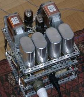
The prototype had two sockets wired in parallel for a quick comparison of both the 6AM4 and 7F8 as drivers. As caps I used 25uF MKP types.
The Tango XE20S is a universal type which allows to select primary impedances of 2.5, 3.5 and 5kOhms.
A group of people got invited for the initial listening. Some other amps were also available for direct comparison. Among them a 300B amp, a PP 46 and also a very elaborate 801A amp.
The amp was an instant hit. It sounded much much better than I would have expected or hoped for. It instantly beated the SE300B and PP46 amps. It had no chance against the 801A amp which was built with 4 times the budget for parts. This was very encouraging and sparked quite some interest among local DIYers. The owner of the 300B amps immediately decided to sell them and switch to 6CB5A.
Before I started to rebuild the amp in a nicer chassis, I spent some more thought on the driver tube. Although the 6AM4 and 7F8 both performed quite well they did not have enough headroom. It was just ok for transformer coupling but would not have been enough for RC coupled versions. So back to browsing the databooks. The 6N7 caught my interest. It would provide similar gain as the 7F8 but more headroom, enough to also use it RC coupled. It is quite linear and has an octal base as the 6CB5A. It is a double triode with common cathode like the 7F8. The prototype got modified for the 6N7 as driver. It has a max plate voltage of 300V so B+ needs to be dropped via a resistor form the output stage. This also serves as decoupling together with a capacitor. A 1kOhm cathode resistor gives an op point of about -6 to -7V on the grid, 6-7mA. That's a good 9-10dB headroom in the driver stage.
A listening test confirmed that the 6N7 was a much better choice as driver. The amp got more refined, more neutral than before, retaining all the sonic qualities which it shares with other excellent single ended concepts.
Now it was time to build a 'serious' version of this amp. Capacitors should be upgraded to oil types. For this purpose I selected ASC X386 series caps. 30uF/440VAC types. Since there was enough interest from other DIYers, I specified a heavy duty power transformer and got a batch of them wound from a local manufacturer. The power transformer was spec'ed such to allow some flexibility for adjustment of the voltages and flexibility to use other tubes as well.
Here is the schematic of the signal section of the final version of the amp with all component values and approximate voltages. No need for 1% parts. Also the exact voltages are not critical. The design has enough headroom to allow for some leeway there.

Let's go through each component and clarify it's purpose and value. Starting at the amps input, we see a 100k resistor to ground. This is providing a reference for the grid of the driver tube and a path to ground. The maximum allowable value for the 6N7 is 500k. 100k is a good value which will present an easy load to almost any preamp. This value can be lowered or increased, 47k or 200k would be fine too. No speacial wattage needed here, 0.5W is fine. This amp is DC coupled at the input. Some amps cap couple the input to provide protection if the preamp has some offset. This amp is fairly insensitive to DC offsets, even a offset of 100mV would not do any harm. If a preamp has more offset it should be replaced anyways. So let's avoid a cap in the signal path here. If you want to have DC protection however, don't hesitate to put one in. Many amps also make excessive use of grid stopper resistors. I left them out. These are not needed for lowish transconductance tubes like the ones in this concept. With careful layout there will be no danger of parasitic oscillation. Again, if you feel better with grid stoppers, put some in. But don't exaggerate. a few 100 Ohms is enough.
The 6N7 has both cathodes wired in parallel, the pin numbers are indicated in the schematic. A 1kOhm cathode resistor takes care of the setting of the operating point. 0.5W or higher can be used for the cathode resistor. What is not shown in the schematic is the connection of Pin 1. This Pin is connected to the envelope if a metal verison of the 6N7 is used. Pin 1 should be connected to ground. Another nice touch about the 6N7 driver: If you compare it's pinout to the 6J5, you will realize that they are interchangeble. The 6J5 will bias up correctly in the same circuit if dropped in. It will just lower the gain. So if there is too much gain in the system, the 6J5 is an easy way to reduce it.
The interstage transformer is a Lundahl LL1660/10mA it is wired 1:1.125 (connection alternative S in the datasheet). The 6CB5A does not need a grid to ground resistor since the secondary of the interstage transformer provides a ground path. This path is very low in DC resistance. In case the output tube is overdriven, which causes grid current it is routed to ground through this low DCR path. This allows the amp to recover quickly from overload conditions. You can experiment with a grid resistor which will terminate the transformer. This usually improves the square wave response. Sonically, I prefer to run transformers unloaded whenever possible.
The 6CB5A is biased with a 1kOhm cathode resistor. Here a high wattage type is needed, 20W or more. This is because of the high voltage across the resistor. It gets quite hot! The 6CB5A is wired in triode mode, the screen grid is connected to the plate through a 100 Ohm screen stopper resistor. Place this resistor as close to the pins as possible.
The output transformer can be any type between 3 and 5 k primary impedance which can be run with 70mA DC. Suitable types: Tango XE20S, Tango FC30-3.5S, Lundahl LL1663, LL1664, LL1682 and others. There are also types from winders like Tamura, Hashimoto, James and many others which would fit.
As mentioned above I selected ASC X386 MP in oil caps. All values are 30uF/440VAC. These caps sound excellent in this amp, better than the MKP types used in the first prototype. Any other cap of similar value and sufficient voltage rating can be used. The exact cap value is not critical. Also higher capacitances can be used.
The 6,8k/20W resistor provides dropped voltage to the driver and decouples the driver supply with the cap following it. The 22k resistor to ground from the driver supply acts as voltage divider together with the 6,8k and as bleeder resistor. It will ensure that the power supply is always discharged when the amp is switched off.
In part 3 I will describe the power supply and also show some photos of the assembly process of the amp.
Stay tuned!
Best regards
Thomas
Hi Thomas,
ReplyDeleteGreat articles! I am looking forward to building this amp and beating my Symphonic Line SS monos :)
Peter from Calgary, Canada
Hi Peter,
ReplyDeleteI'm sure you will love the amp! If you have questions don't hesitate to ask. Also if you have difficulties finding any of the parts, I can supply most of them.
Thomas
Hi Thomas,
ReplyDeleteI have read all of the articles and have to say that you have done fabulous job explaining this design (I think I understand it). I will be curios to see the PS and will definitely take you up on your custom Mains (are they with two independent screens, as well :)?) and chokes. I am assuming that your future posts will talk about filament bias and some of your other famous design tricks.
I am more in the cost no object camp and will be curios to see at what point I can start building this amp. I have to admit that I have built/modified DAC (Lampizator vs AudioNote 3) and preamp but have been too intimidated by amps. You are making it look too easy.
Best,
Peter
Hi Peter,
ReplyDeleteYes I also use the power transformers with two screens and grain oriented cores for this project. They are universal and can be used for a lot of diffeent amps. I have these for all primary voltages and also in different sizes with secondary currents of 100, 200 and 400mA.
The 45 / 2A3 all DHT amp which I posted today is also based on the same basic principle as the 6CB5A amp.
Thomas
Hi Thomas,
ReplyDeleteI would like to test my understanding of the choice of the primary impedance of Transformer (how did you arrive at 3K to 5K range).
After looking at past issues of SP and RHD3, "Magic" formula was presented to allow for calculation of Primary impedance of OTX(from Radiotron Handbook)
ZPri= 0.9(B+ / Plate Current)
0.9 x(425/70) = 5.4K or 0.9x(425/75)= 5.1K
I am confused as to why and how 3 and 3.5K TX can be used in this application. Is it because of the wide headroom of the design (can't see the load-lines for triode operation of the tube)
I apologize if this is simplistic question, and appreciate clarification.
Peter
Hi Peter,
ReplyDeletethere is no 'magic' formula for calculating the primary impedance. In fact there is nothing 'magic' at all about tube electronics, although some people try to make others believe this ;-)
There is a rough guideline which says the primary impedance should be 3 times the plate resistance of the tube. If you want more power go down to 2*rp at the expense of higher distortion. If you want less distortion and a better damping factor (lower output impedance) go up to 5*rp or even higher.
But what actually is the load the tube sees? It is the load at the secondary side of the transformer multiplied by the square of the turns ratio of the transformer. But have a loog at the impedance curve of a typical 8 Ohm speaker it varies anywhere between 6 and 30 Ohms, sometimes even more. If such a speaker is connected to a 8 Ohm tap of your outputtransformer, and the transformer is a 3k:8 Ohm unit, your output tube will see a load between 2250 and 11250 Ohms depending on the frequency. What is the correct load in this situation? As you can see in a real life application with a real world loudspeaker, the actual impedance the output tube sees is quite arbitrary!
Consider this next time if somebody insists that a certain tube needs a very exact load impedance for best sound.
The above is a very simplisitc view, I just wanted to make the point about the fuzzyness you have in the load impedance anyways. On top of this you have the primary inductance, leakage inductance and wiring capacitance which also plays a role.
Best regards
Thomas
Just wanted to add: The rp of the 6CB5A is about 1kOhm. Plate curves can bee seen in my post about the 6CB5A tube
ReplyDeleteThank you for clarification and explanation (I have learned something new today).
ReplyDeleteI guess 6cb5a rp is different when run in triode mode.
I have also missed the fact that Gordon Rankin used this formula to aproximation primary inductance of pentode based amp (A single "807" amplifier from SP) (formula is on page 567 of RDH4).
Thanks again,
Peter
Hi Thomas,
ReplyDeleteThanks for the detailed explanation of this circuit from concept to production.
Can I use a pair of 40H/60ma chokes in place of 20H/100ma chokes ? I also have a pair of LL1692 chokes (1:1.75) - could I use it in place of the LL1660 ?
Regards,
nikhil
Hi Nikhil,
ReplyDeletethe current rating of the 60mA choke is not sufficient. The LL1692 transformer is usable if it is gapped for 10mA, if it is the 18mA version it will have too low primary inductance. If you have the 10mA version use it either in 4:3.5 or 3.5:4 configuration. I can supply you with the right chokes and transformers for this project.
Best regards
Thomas
HI Thomas,
ReplyDeleteyou presented a very interesting SE amp! My planning previous to your concept was to build an SE amp based on PL/EL509 which is as well a TV tube as yours. I use power sensible loudspeaker (Cabasse Egea3) - with PL509 amp I've tested and does fed enough power to LS.
Two questions:
1) What typical output power will provided?
2) Where to get Iron to by (bavaria)?
Regards,
matthias
Hi Mathias,
ReplyDeletea 6CB5A in SE will provide about 7W-8W.
You can get all these parts for example from me ;-)
Thomas
Thomas,
ReplyDeleteDo you have a preferred (best sonics) manufacturer for the 6N7 tube? Also, any sonic differences between metal and glass types?
Cheers,
-- josé k.
Hi Jose,
ReplyDeleteno I don't have a preference. I'm not a tube roller ;-)
Thomas
Thomas,
ReplyDeleteHave you tried the 6Y7? Except for heater current, it has similar specs to the 6N7.
Cheers,
-- josé k.
Hi Jose,
ReplyDeleteno haven't tried that yet. The 79 is another candidate.
So many tubes so little time :-)
Thomas
Hi Thomas,
ReplyDeleteGreat series, I learned a lot!. Was wondering if you could kindly clarify something for me:
The operating point for the 6N7 was selected at -6V on the grid, as per the datasheet. My understanding is that it's a good idea to not allow the grid to go more positive than -1V (to avoid grid current). This would mean +/- 5V max swing around the Operating point (-6V), i.e from -1V to -11V. 10V peak to peak, 3.5V RMS which is about 3 times more than typically needed, i.e. headroom of 9-10 dB, just like you mentioned!
My problem is I can't find what the plate curves look like around -11V on the grid - none of the datasheets I could find shows that... Are you just extrapolating what you see on the datasheet and then rely on the practical test?
Thanks a lot in advance, and thanks for the great blog!
Cheers,
-Victor
Hi Victor,
ReplyDeleteyes I always try to get as much headroom as possible in the driver. Except in my latest low cost version of this (recent posts on my blog) where I had to compromise headroom).
I always look at the plate curves on my curve tracer to double check.
Best regards
Thomas
Very interesting work. You are just showing that a great designer can make a great amp from any decent tube with useful parameters for audio. Just what Tim de Paraviccini kept on repeating for ages and no one trusted him.
ReplyDeleteStill, I have a slight feeling you are too subjective about 300b. Can not be the that whole history of tube audio was wrong about it. I too have heard better amps based on less hyped tubes (like 6C33C) but a good, no-compromise 300b amp is there with the best you can get from tubes.
I know 6CB5A is your trade mark tube/amp now, but would really love to hear what prevented you from making a 300b amp that sounds better (for you)? Lack of motivation or tube restrictions?
All the best!
Hi!
DeleteThanks for your comment.
May be my comments about the 300B are too harsh. I do think it is a great tube and well implemented makes for an great amp. I already built several 300B amps. See for example here for a review:
http://www.hifiwigwam.com/showthread.php?56853-Thomas-Mayer-amps/page2
The 6CB5A concept is meant as an alternative when on a restricted budget.
Best regards
Thomas
What about 6146 tube and a G2 at 200 volts?
ReplyDeleteTikky koot
Hi!
DeleteI used the 6CB5A triode connected. What you are proposing is pentode operation. Quite different. I have no experience with the 6146
Best regards
Thomas
Hi Thomas, thank you for this nice circuit! Help me please, what would be a nice operating point for 6CB5A with a 55 mA, 5k OPT that I have to hand? Would 5 watts still be possible?
ReplyDeleteWhat circuit values would change in the output stage of your schematic to suit my operating point?
Many thanks in advance.
Hi Grant,
DeleteThis OPT would be better for a project with the 6GE5 which I just presented as tube of the month Oct 2014. For that tube I proposed an op point of 55mA and 5k load. I will come up with a circuit for that amp soon
Best regards
Thomas
Fantastic, my breath is on hold!
Deletedude eye like your frame setup, where do you buy those? They show off the tube porn so well...!
ReplyDeleteYou can buy those from me as well as other parts I use for my amp building like transformers, caps...
DeleteHello Mr Mayer
ReplyDeleteFirst of all let me applaud your efforts in explaining in such a lucid way. It really matters
Would 6J5 suitable in place of 6N7? Same Alt S? Thanks.
yes that would work as well
Delete